Hydraulic shock occurs when oil rapidly starts or stops flowing in a hydraulic system. The oil flow rate in the pressure line of systems below 200 bar is usually 4.5-6 meters per second. In systems above 200 bar, the flow rate can be as high as 9 meters per second. Shock can also occur when an external force acts on a hydraulic cylinder or motor.
Unlike air, hydraulic oil is generally considered to be non-compressible. Oil will only compress one-half of a percent when pressurized to 70 bar. When a pressure spike occurs in the system, the pressure can increase four or five times above the normal operating pressure. Since the average duration of a shock spike is 25 milliseconds, the pressure gauge cannot respond fast enough to give an accurate indication. Pressure transducers are normally used to record pressure spikes.
Shock spikes that are not properly dampened or absorbed can result in leakage and damage to the lines and components in the system. This article will look at three things that can be done to reduce hydraulic shock.
Install an Accumulator
A hydraulic accumulator is pre-charged with dry nitrogen. Some type of separating device such as a piston, bladder or diaphragm is used to separate the nitrogen from the hydraulic oil inside the accumulator. A bladder (Figure 1) or diaphragm type is recommended to absorb shock. Both of these accumulators contain rubber elements that will be compressed when the hydraulic pressure rises above the dry nitrogen pre- charge. Depending on the system, the accumulator should be pre-charged to 7 bar below to 15 bar above the maximum operating pressure in the system. Accumulators that are used for shock can be small in size, usually 1 to 5 liters.
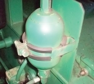
The accumulator should be installed as close as possible to where the shock spike is occurring. For example, if the pressure spike takes place when a cylinder fully extends, the accumulator should be installed near the port connected to the full piston side of the cylinder.
Accumulators are often used to absorb high flow surges in return lines. In this case, the pre-charge should be lower than the maximum pressure rating of any return filters or heat exchangers located downstream. Any time an accumulator is used in the pressure line, an automatic and/or manual dump valve should be installed to bleed the hydraulic pressure down to zero once the system is turned off.
Add Directional Valve Pilot Chokes
A typical two-stage, hydraulic-piloted, solenoid- controlled directional valve is shown in Figure 2. The valve contains pilot chokes, which are located in the block between the pilot valve on top and the main spool on the bottom. The block includes two flow controls connected in a meter-out arrangement and two bypass check valves. When either of the pilot valve solenoids is energized, pilot pressure is ported through one of the internal check valves and to one side of the main spool.
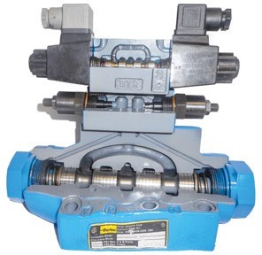
As the spool shifts, the oil in the pilot cavity on the opposite side flows through the flow control and back to the tank through the pilot valve. The setting of the flow control determines the rate that the main spool shifts. By allowing the spool to gradually shift, the pump volume is gradually ported through the valve and to the system.
Use Crossport Relief Valves
Crossport relief valves are commonly used with hydraulic motors when it is necessary to stop a load relatively quickly. The main issues with crossport relief valves are that they are usually omitted from the system, are set too high or are mounted too far from the motor.
By using these three remedies, you can greatly reduce the hydraulic shock in your systems and help to eliminate oil leakage at your plant.