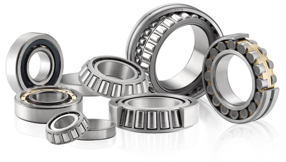
The basic purpose of a machine bearing is to provide a near frictionless environment to support and guide a rotating shaft. Two general bearing styles are utilized at this time: the journal bearing and the rolling element bearing. For lower horsepower and lighter loaded machines, the rolling element bearing is a popular choice.
Bearing designs
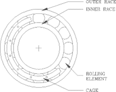
Rolling Element Bearings have four components: an inner race, an outer race, rolling elements, and a cage to support, space, and guide the rolling elements. All rolling element bearings have one thing in common: all parts must be always in physical metal to metal contact. Installation instructions specify the amount of bearing pre-load to maintain the component contact.
Rolling element bearings have some unique concerns not found in journal bearings. A rolling element bearing will always force a vibration node. Because of the metal-to-metal contact, this bearing will provide very little vibration damping. Although these bearings are a very precisely machined part, they have a limited lifetime. Each component of the bearing will generate specific frequencies as defects initiate and become more prevalent.
Vibration Monitoring Applications
Rolling element bearings, by their design and installation, provide a very good signal transmission path from the vibration source to the outer bearing housing. Τhese bearings require monitoring of the unique bearing frequencies generated by the various parts of the bearing, in addition to the rotor fault frequencies.
Bearing Frequency Calculation
Although modern rolling element bearings are very precisely machined, they do have micro-defects which are potential sites for future damage. Due to the precise tolerances, improper installation practices can reduce bearing life. Extensive information has been compiled about bearing defect frequencies.
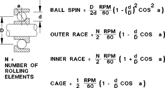
The figure lists the bearing defect frequency formulas for a defect on the balls or rollers, outer race, inner race, and cage. The assumption for these formulas is that the outer race is stationary while the inner race rotates.If the bearing dimensions are known, the individual bearing defect frequencies can be calculated precisely, or a general rule of thumb can be applied. Using the generalized form, the inner race frequencies would be N x RPM x 60% and the outer race frequencies would be N x RPM x 40%. If the bearing manufacturer model numbers are known several computer programs are available to calculate the necessary frequencies.
Failure monitoring
This style of bearing is typically monitored using a case mounted transducer: an accelerometer or velocity pickup. A displacement sensor observing the shaft relative vibration would show little, if any, vibration due to the vibration node created by the bearing.
Viewing the vibration spectra, useful information can be obtained about the failure modes. This figure shows the spectrum frequency content during four stages of bearing failure. A normal bearing or newly installed bearing will show no frequencies except those associated with shaft phenomenon such as balance or misalignment.
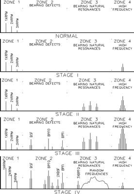
Stage I has some very high frequency content. This zone is in the ultrasonic region which requires a sensor specifically designed to detect in this region. Special circuitry filters pass only those signals. Physical inspection of the bearing at this stage may not show any identifiable defects. However this stage can be detected with ultrasonic transducers.
Stage II begins to generate signals associated with natural resonance frequencies of the bearing parts as bearing defects begin to “ring” the bearing components. A notable increase in Zones 3 and 4 region signals is associated with this stage. Beginning signs of defects will be found upon inspection.
Stage III condition has the fundamental bearing defect frequencies present. These frequencies are those discussed previously in this paper. Harmonics of these frequencies may be present depending upon the quantity of defects and their dispersal around the bearing races. The harmonic frequencies will be modulated, or side banded, by the shaft speed. Zone 4 signals continue to grow throughout this stage.
Stage IV is the last condition before catastrophic failure of the bearing. This stage is associated with numerous modulated fundamental frequencies and harmonics indicating that the defects are distributed around the bearing races. Due to the increased degradation of the bearing the internal clearances are greater and allow the shaft to vibrate more freely with associated increases in the shaft frequencies associated with balance or mis- alignment. During later phases of stage IV, the bearing fundamental frequencies will decline and be replaced with random noise floor or “haystack” at higher frequencies. Zone 4 signal levels will decrease with a significant increase just prior to failure.
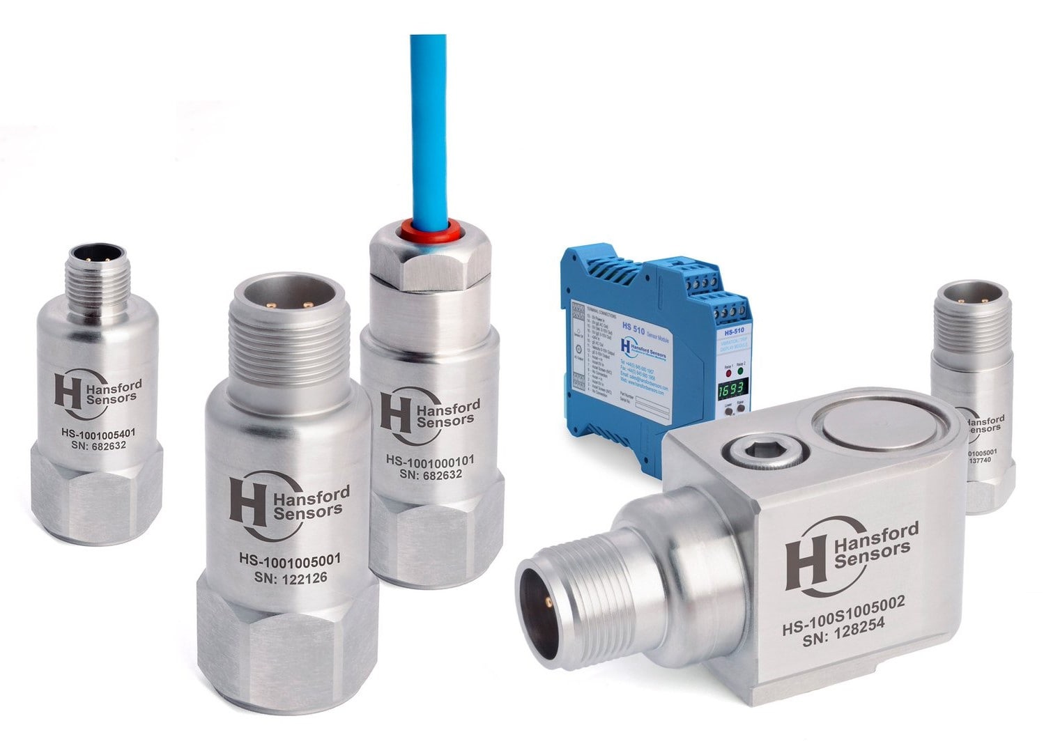
Vibration sensors
We offer vibration sensors and analysis tools.
More
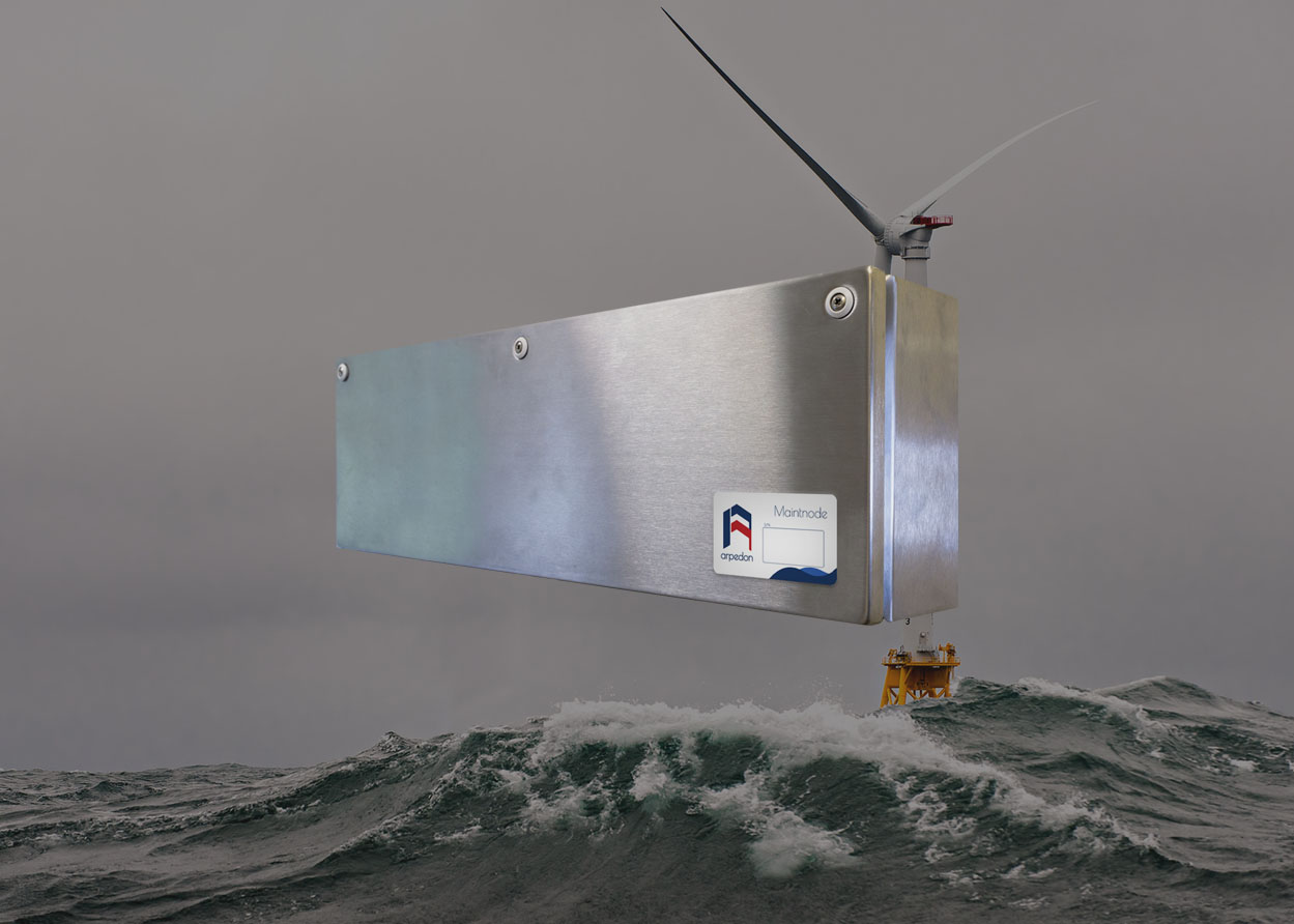
Maintnode
A permanently installed system for the most demanding tasks. Multiple sensor measurements and data from the production systems provide a complete view for the condition of the equipment.
More